Configuración
 Entrega rápida
 Tipos de pago


 Producto del mercado

Efficient Robot Motion with Toshiba Motor Drivers MOSFETs Isolation
2026-10-01
In a robot joint, there is no room for a fan, so the heat the drive stage generates has to escape through the housing. Keeping losses low requires a driver that appropriately shapes the current waveform and MOSFETs that carry it efficiently. The high-voltage power stage also requires isolation from the control electronics to preserve signal integrity and protect the operator. Toshiba supplies all three (drivers, MOSFETs, and isolation) and provides a reference design showing how they all work together.
Drivers for brushed, brushless, and stepper motors
A suitable driver depends upon the motor type. Fortunately, Toshiba’s brushed DC portfolio offers more than 90 ICs. For a straightforward brushed DC motor joint, the TB67H453FNG (Figure 1) is a practical starting point. It is a PWM-chopper H-bridge driver operating from 4.5 V to 44 V at up to 3.5 A. Its integrated output MOSFETs have a typical on-state resistance of 0.3 Ω on both the high and low sides. The device draws 1 µA in standby mode and comes in an HTSSOP 16-pin package, and its built-in current monitoring makes it well suited to cleaning robots and other small household platforms. A lower-voltage variant, the TC78H653FTG covers 1.8 V to 7.5 V for battery-powered devices.
 Figure 1: The TB67H453FNG brushed DC motor driver. (Image source: Toshiba)
When a joint uses a brushless DC motor instead, the driver must add commutation logic rather than relying on a simple bridge configuration. The TC78B009FTG handles this as a sensorless pre-driver controlling six external MOSFETs, offering rectangular wave commutation at 120, 135, 142.5, or 150 degrees, with closed-loop speed control stored in onboard non-volatile memory. The TC78B027FTG takes a different approach, utilizing a single Hall sensor with sine-wave output and Intelligent Phase Control, which automatically aligns the driving voltage and current phases to improve efficiency. These pre-drivers operate closed-loop, though neither performs full field-oriented control (FOC).
For joints that require torque control across their full speed range, closed-loop commutation is not enough and FOC becomes necessary. Toshiba’s industrial platform for FOC is the TXZ+ M4K microcontroller, an Arm® Cortex®-M4F running at 160 MHz, whose hardware Advanced Vector Engine Plus executes the Clarke and Park transforms and the PI loop deterministically rather than consuming CPU cycles. Toshiba has also begun sampling the SmartMCD TB9M030FG, which integrates an Arm Cortex-M0 core, gate driver, and vector engine for sensorless FOC from zero speed.
Not every robot joint needs continuous rotation. In applications where a joint holds its position rather than turning continuously, stepper motor control applies. The TB67S128FTG operates to 50 V and 5 A with combined on-resistance around 0.25 Ω, supporting full step through 1/128 micro-stepping natively and extending to 1/1024 through its serial interface.
Advanced micro-stepping and load-adaptive current
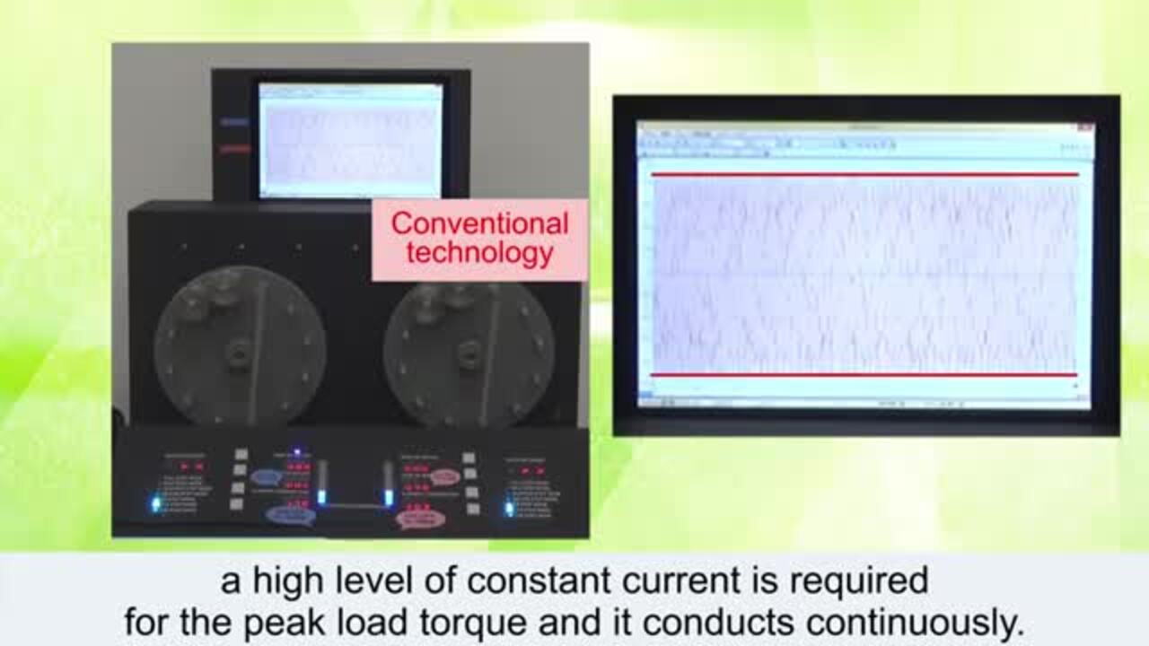
The 1/128 step divisions set the step count, but do not guarantee smooth motion on their own because micro-stepping resolution alone is not enough. The current waveform also has to hold its sinusoidal shape across each step, and the drive current has to match the actual load.
The TB67S128FTG (Figure 2) handles both requirements and reduces the external component count in the process. Its Active Gain Control detects the induced voltage during operation to infer the load and then adjust the drive current accordingly, lowering heat and power draw compared with running at a fixed conservative current. Advanced Dynamic Mixed Decay manages current decay across each step, while the Advanced Current Detection System eliminates the external sense resistors.
 Figure 2: The TB67S128FTG stepper motor driver. (Image source: Toshiba)
Building on these capabilities, the TB67S579FTG offers Advanced Micro-stepping Technology, combining second-generation Active Gain Control with an Automatic Wave Generation System that produces micro-stepping from a single clock input, and Continuous Micro-stepping that generates a smooth sinusoidal current waveform to reduce vibration and audible noise at low speed. Noise is not the only consequence of a distorted waveform; the same distortion appears as torque ripple in a joint. Holding the waveform smooth therefore resolves both issues, allowing a service robot moving a payload through an occupied corridor to run quieter and hold its motion more steadily.
MOSFETs and the conduction vs. switching trade-off
Between the driver and the motor are six MOSFETs, and their characteristics determine how much of the input power reaches the windings versus how much is lost as heat. The MOSFETs in a motor bridge dissipate power in two ways: conduction loss scales with on-resistance and the square of the phase current, dominating at high torque and low speed, while switching loss scales with gate and output charge and with switching frequency, dominating at high speed and light load. A robot joint moves through high-torque acceleration and high-speed cruising within a single trajectory, so optimizing for one loss mechanism at the expense of the other results in a joint running hotter than necessary across half its operating range.
The two loss mechanisms also conflict in silicon. Lowering RDS(on) generally means a larger die which carries more gate charge, raising switching and drive loss. However, Toshiba created a compromise using the product of on-resistance and gate charge, where a lower figure indicates a device improves both rather than trading one for the other. Its low-voltage trench generations, U-MOS IX-H through U-MOS11-H, target that balance, and the high-voltage DTMOS super-junction families do the same at mains-connected voltages.
As an example, the TPW3R70APL (Figure 3) is rated at 100 V and 150 A in a DSOP Advance package, specifying 3.1 mΩ typical on-resistance at a VGS of 10 V, 21 nC switching charge, 74 nC output charge, and 0.88°C/W channel-to-case thermal resistance. The low milliohms keep conduction loss down through the high-torque portion of a move, while the modest charge figures keep the switching loss down through the high-speed portion.
 Figure 3: The TPW3R70APL N-channel MOSFET. (Image source: Toshiba)
Isolation between control and power domains
The switching stage is the noisiest and highest-voltage part of the circuitry. As it shares a housing with the control electronics and communication interfaces, isolation is required to separate these two voltage domains, block ground loops, and keep switching transients from reaching the control side.
Toshiba’s gate driver photocouplers, e.g., the TLP5791H, TLP5794H, and TLP5795H are designed to carry the switching signal across the isolation boundary, covering the 1 A to 6 A drive class with common-mode transient immunity up to 40 kV/µs, preventing false switching when the inverter’s dV/dt couples back across the barrier. Building on that base, the TLP5222 adds overcurrent detection with isolated fault feedback and an active Miller clamp, while the TLP5814H targets SiC devices.
Current sensing crosses the isolation boundary in the opposite direction, since phase current has to be measured on the high-voltage side and reported to a controller on the low-voltage side. The TLP7820 and TLP7920 optically coupled isolation amplifiers handle this using a delta-sigma converter, specifying 0.02% typical linearity, 20 kV/µs common-mode transient immunity, and 5,000 Vrms minimum isolation. Typical applications include inverters, servo amplifiers, robots, and power supplies.
Toshiba’s servo drive reference model
After choosing the right driver, MOSFETs, and isolation, it is imperative to understand how they work as a system. Toshiba demonstrates this integration with its Servo Drive Reference Model, designed for robots, cobots, SCARA arms, and automated guided vehicles. The design pairs the M4K microcontroller with its hardware FOC engine, PMD timers, and 32-bit encoder input, with a low-voltage power board built on six TPW3R70APL MOSFETs, capable of driving 48 V BLDC motors with up to 200 W.
The design isolates the USB-to-UART link and uses a photorelay to switch the motor brake from the low-voltage side, while separate feedback boards accept differential encoders and resolvers. Toshiba demonstrated the model on a modified AR3 robot arm fitted with 24 V BLDC motors, well within the board's 48 V capability, driving 1:50 or 1:64 gearboxes. On that platform, it achieved positioning accuracy of 0.2 to 0.3 degrees per axis and acceleration of 300 rad/s².
Conclusion
Sourcing your drivers, MOSFETs, and isolation from a single supplier removes the guesswork of matching devices across vendors. Toshiba’s reference design takes that further by providing a documented starting point, with the hardware arrangement and its measured performance already published.
For more information on Toshiba’s motor drivers, MOSFETs, and isolation devices, please visit Toshiba's power solutions page on DigiKey.
Descargo de responsabilidad: Las opiniones, creencias y puntos de vista expresados por los autores o participantes del foro de este sitio web no reflejan necesariamente las opiniones, las creencias y los puntos de vista de DigiKey o de las políticas oficiales de DigiKey.